Full Lug End Double Offset Carbon Steel Two Eccentric Butterfly Valve


- Availability: In Stock
- Product Model: LTD72F
Full Lug End Double Offset Carbon Steel Two Eccentric Butterfly Valve
Introduction of Double Excentric High Performance Butterfly Valve
TEKO Wafer and Lug Type high performance butterfly valve are double excentric high performance design. The unique design makes the disc move back and away from the body seat during the opening movement. The double eccentric design decreases the seat friction, which results in an extension of the valves life span and lower operating torques. If repair is needed, the seat can be replaced easily without removing the valve shaft. All high performance seats are exchangeable.
These TEKO butterfly valves are bi-directional, but do have a preferred flow direction. It is however strongly recommended to install the valve in the preferred flow direction.
Speicificaitons
|
Wall Thickness |
API 609 |
|
Pressure - Temperature Ratings |
ASME B16.34 & API 609 |
|
General Valve Design |
API 609 (Cat. B) & ASME B16.34 |
|
End to End Dimensions |
ASME 609 |
|
Flange Design |
ASME B16.5 |
|
Materials |
ASTM |
API 607 Fire Safe Seat- Working Principle
Figure 1. DISC OPEN, Normal Operation
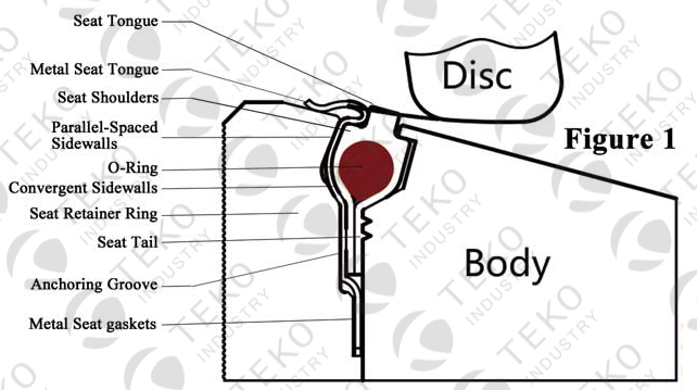
In Figure 1, the disc and seat assembly are not engaged. In this position, the metal seat acts to keep the soft seat inside the seat cavity while the soft seat shoulders seal the cavity form exposure to the process fluid. (The O-ring is under tension and imparts a load against the soft seat.)
The soft seat is protected from abrasion and wears because it is recessed inside the seta cavity area. The O-ring is isolated from exposure to the fluid because it so completely encapsulated by the seat tails which as a (soft) gasket in the anchoring groove area. The metal seat gasket adds further high temperature protection past the anchoring grooves.
Figure 2 DISC CLOSED, Normal Operation
In figure 2, the disc and seat assembly are engaged; both the metal seat and the soft seat are in contact with the disc. Under little to no pressure conditions, both seats are self-energized. The disc edge, with a larger diameter than the seat tongues, moves the seats radially outward; the metal seat shaft, with a mechanical and dynamic flexibility, is designed to be hoop-loaded and impart a spring force against the disc, while the soft seat O-ring is stretched and flattened (without deformation of the material) and imparts a mechanical pre-load again the disc.
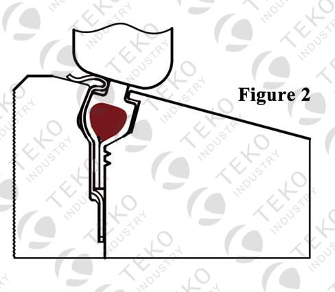
With increased line pressure, the process fluid enters the cavity sidewall area and applies loads against the seat sidewalls. The cavity design allows the seats to move toward the downstream sidewalls, but confines and directs the movement radially inward towards the disc; the higher the pressure the tighter the seal. The symmetrical shape and angle of the cavity permit the seal to be bi-directional.
Figure 3, DISC CLOSED, After Fire (Seat Upstream)
After a fire, with partial or complete destruction of the soft seat, the metal seat maintains metal-to-metal contact with the disc and restricts leakage of the process fluid in conformance to industry fire-safe requirements. With little or no line pressure, the spring force and hoop load of the metal seat maintain a “line contact” seal against the disc edge. Under higher pressures, the process fluid enters the cavity sidewall areas and applies loads against the seat sidewalls (Figures 3). The geometry of the metal seat permits the seat to move axially, but directs the movement radially inward toward the disc. The higher the pressure, the tighter the line contacts seal.
Graphite gaskets, on both sides of the metal seat tail, seal the anchoring groove and prevent leakage of the process fluid.
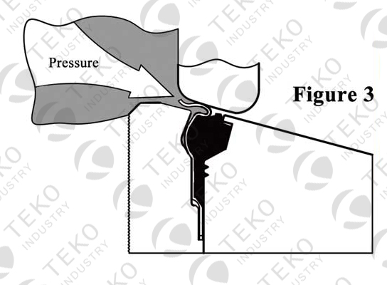
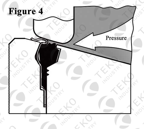
Figure 4 DISC CLOSED FIRE, After Fire (Seat Downstream)
The Fire Safe HPBFV is bi-directional; however, modifications are required to operate for bi-directional dead and service. The angle and shape of the cavity and metal seat maintains metal-to-metal contact in the event of partial or complete soft seat destruction with line pressure in the reverse direction (Figure 4)
While the preferred flow direction is “seat upstream” (SUS), the bi-directional seat design is both self-energized and pressure-energized if the flow direction is seat “downstream” (SDS).